Engineering
Manufactured to be Tested, Not Just Installed
A high-pressure water mist system fails the day it is needed if any component in the flow path was under-specified. Every Mistelix system is built to be verified, not just assembled — and it begins on paper, as a design basis a consultant can check. The figures below walk the water path end to end — tank, filtration, pump, and the nozzle that does the actual work.
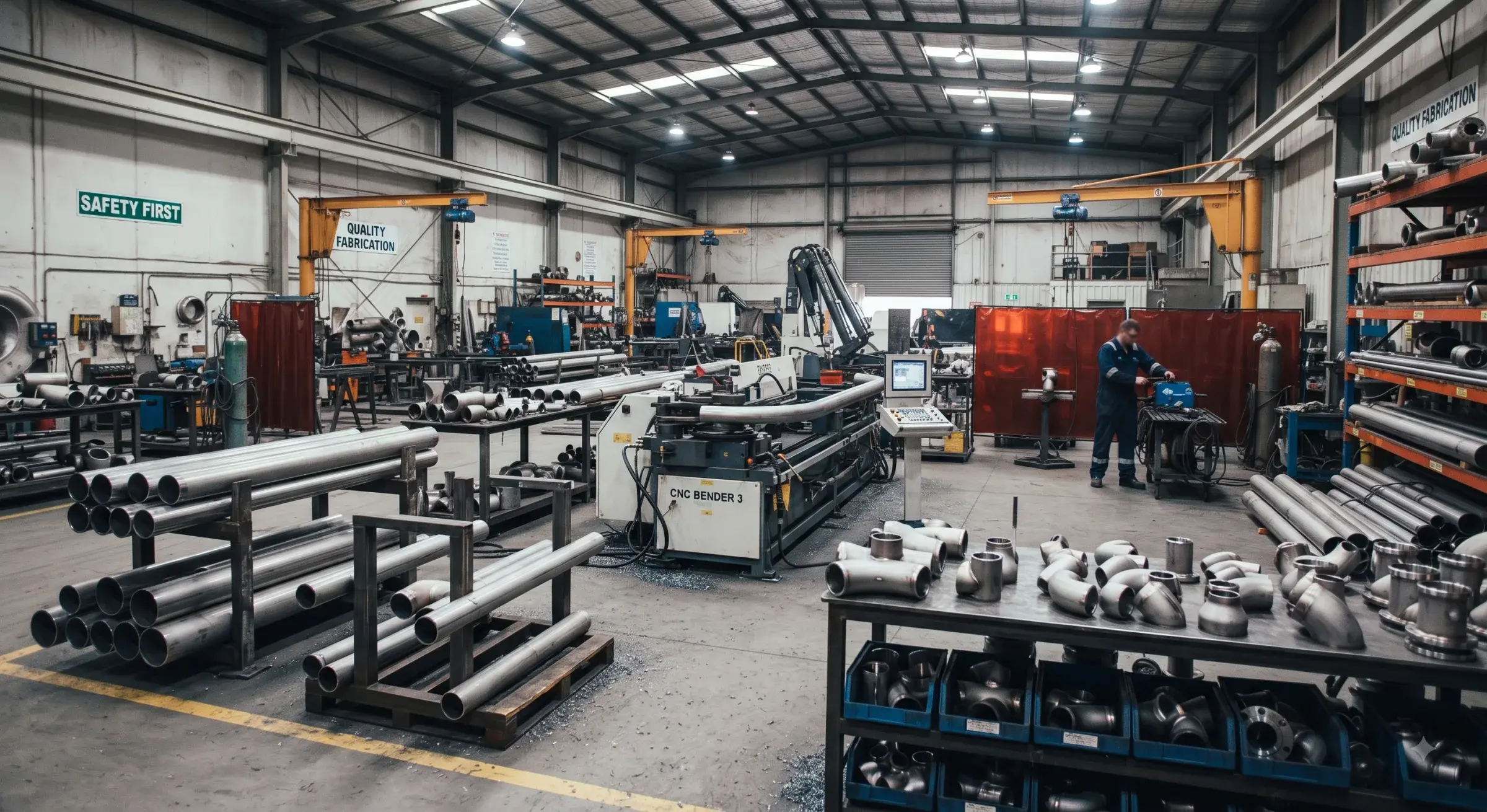
Images on this page show representative equipment and workshops, not Mistelix facilities or installations. Figures are illustrative schematics, not manufacturing drawings. Production hardware may differ from what is shown.
Method
Every project starts on paper
Before a pipe is cut, a Mistelix project exists as a written design basis — how the system is designed and why, issued for review before bid, with every assumption flagged for confirmation and every deviation from the specification stated rather than buried. The consultant and the authority who approve the system see the basis for every number in it.
The water path · 1 of 4
Storage: the tank the system stands on
Suction design decides whether a pump gets the water it was sized for. The tank carries a vortex breaker over the outlet, a low-level switch wired to the controller, and a sight gauge that lets an operator confirm capacity at a glance — no instrumentation needed.
Illustrative schematic · not a manufacturing drawing · production hardware may differ
The water path · 2 of 4
Filtration: duplex, because nozzles are unforgiving
A mist nozzle orifice is under a millimetre across — one particle of pipe scale can take a nozzle out of duty. A duplex basket filter with a changeover valve means one basket is always in service while the other can be opened and cleaned, so filtration never comes offline with the system armed.
Illustrative schematic · not a manufacturing drawing · production hardware may differ
The water path · 3 of 4
Pressure: the pump skid
A water-lubricated high-pressure pump driven by an electric motor on a common baseframe delivers the 50–140 bar the nozzles are designed around. Water-lubricated means the water being pumped is the pump’s own lubricant — no oil in the pump to leak into the system or to change — and a relief valve protects the line. Pump skids, valve manifolds and nozzle assemblies are machined and assembled to the tolerances a 50–140 bar system demands, with every weld and fitting traceable to the assembly record.
Illustrative schematic · not a manufacturing drawing · production hardware may differ
The water path · 4 of 4
Atomisation: inside the nozzle
Everything upstream exists to feed this component. Water enters through the strainer, is spun by the swirl insert, and leaves the orifice as a full cone of droplets under 200 µm — the droplet size that cools, displaces oxygen, and blocks radiant heat. The cross-section shows what a photograph can't.
Illustrative schematic · not a manufacturing drawing · production hardware may differ
Hydraulics
Calculated, not asserted
Every flow and pressure in a Mistelix design is calculated and shown, not asserted: the water the nozzles need, the pump head required to deliver it to the most remote zone, the power that takes, and the storage the discharge duration demands. Because the arithmetic is visible, a consultant can check it.
Illustrative schematic · not a manufacturing drawing · production hardware may differ
Supply topology
Fed from two directions
A looped ring main feeds every zone from both ends, so no nozzle depends on a single run of pipe. Sectionalising valves let a damaged length be isolated without taking the loop out of service, and on detection the fire zone and one zone either side open together, so a plume pushed downstream by tunnel ventilation stays inside the wetted envelope.
Illustrative schematic · not a manufacturing drawing · production hardware may differ
Illustrative schematic · not a manufacturing drawing · production hardware may differ
Controls
Cause and effect, written down
Detection locates the fire, opens the right section valves and starts the pumps; on reset the system purges and re-arms itself. That sequence is written down as a numbered deliverable, the control panel integrates with the plant’s own control system, and every signal exchanged is scheduled for review.
Illustrative schematic · not a manufacturing drawing · production hardware may differ
Quality
Hydrostatic testing
Every pump skid is hydrostatically tested to 1.5× working pressure before it ships — the same margin fire protection standards require for pressure-retaining components, verified in our own facility rather than assumed from a supplier datasheet. Nozzles are proof-tested above the system’s design pressure before assembly.
Component pedigree
Sourcing and materials
Pumps, valves, instruments and control panels are sourced as catalogue items from established manufacturers with a track record in high-pressure fluid handling. Nozzle wetted parts are marine-grade SS316L with a ceramic orifice disc for wear resistance and fluoroelastomer seals; nozzles self-purge on shutdown so orifices resist scale and fouling over the system’s design life.
Facility
Where we build
Mistelix manufactures and tests in its own facility. Facility details, capacity information and quality documentation are available to customers and project consultants on request.
Next step
Talk to us about your project
Send us the application, the governing standard and any drawings you have. An engineer responds with a system concept and hydraulic basis — not a sales pitch.
Request system concept