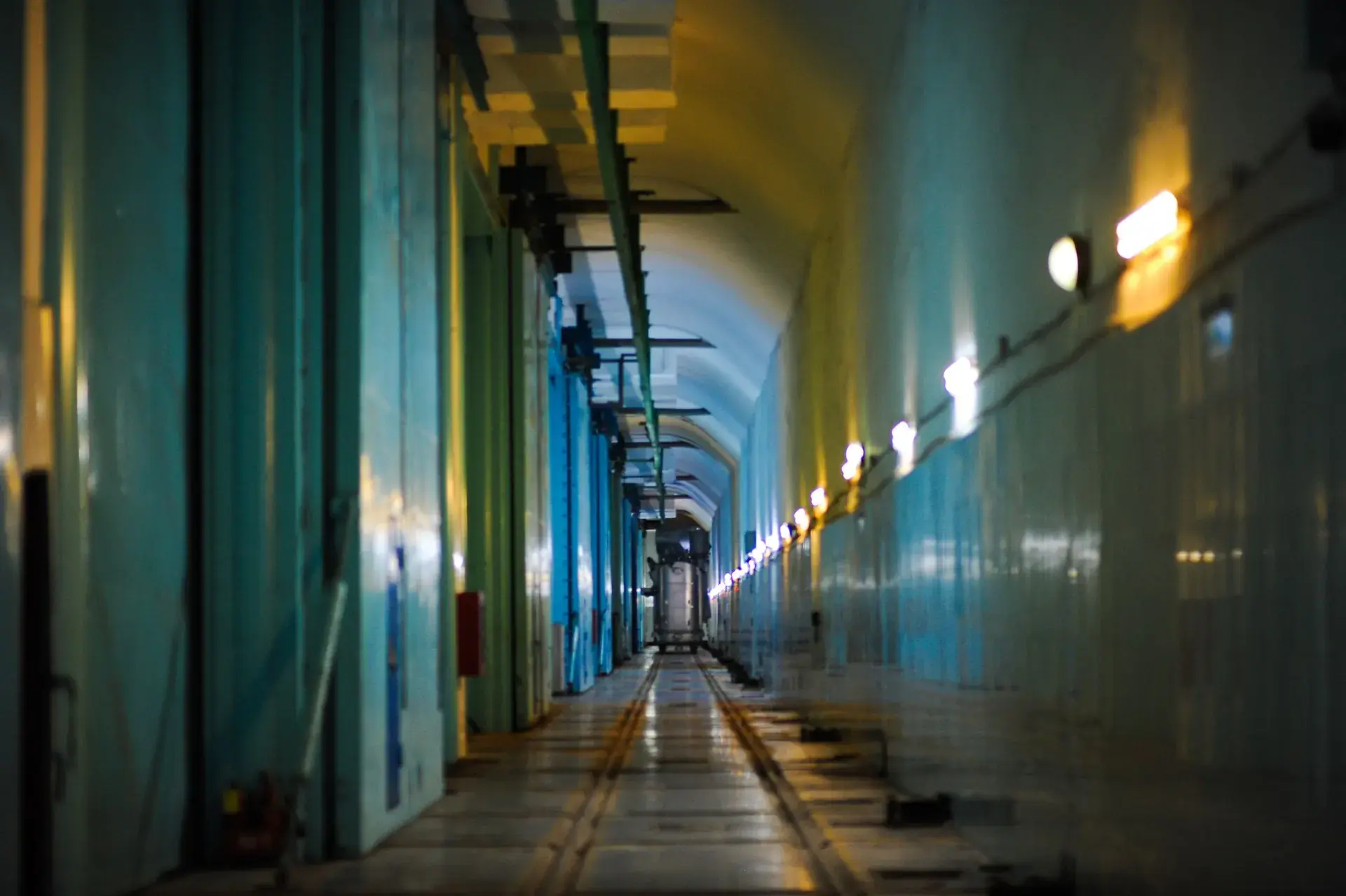
Cable tunnels are one of the few applications with their own dedicated fire test protocol in the EN 14972 series: Part 11, test protocol for cable tunnels for open nozzle systems, built on an established VdS test method. For metro operators and power utilities evaluating water mist for cable galleries, Part 11 is the reference that separates tested systems from claimed ones.
The fire being simulated
A cable fire is unlike a vehicle or liquid-fuel fire. Cable insulation is a dense, self-sustaining fuel that burns along the length of a tray, re-ignites readily from retained heat, and produces heavy smoke in a corridor that is usually unmanned. A suppression system cannot rely on anyone being present: detection, activation, and knockdown have to complete the entire job.
The Part 11 test assembly reflects this. A test corridor at least 2.35 m wide and 2.20 m high carries stacked horizontal cable trays — eight levels — loaded with real cables, ignited from below by a propane gas burner. Thermocouples record the temperature sequence throughout, averaged over 30-second windows.
The pass criteria
The pass criteria in the protocol are concrete and unforgiving:
- Temperature knockdown — temperatures in the fire test room must fall below 100 °C within 5 minutes of the extinguishing system activating.
- No sustained combustion — no later than 15 minutes after activation, no flames or embers may be visible on any cable, verified visually and with a thermographic camera.
- Damage limitation — after the test, the cables of each tray must not be damaged over a length of more than 1 metre on either side of the fire location.
Those three numbers describe exactly what a utility wants from a suppression system: kill the temperature fast, leave nothing smouldering, and confine the loss to a short, repairable section of tray rather than a full gallery re-pull.
What "covers" means — and its limits
A system that passes Part 11 is approved for cable tunnels and ducts within the dimensions and wind velocities tested. That scoping matters when reviewing a supplier's documentation: a test in a 2.4 m corridor at low airflow says nothing automatic about an 8 m ventilated gallery. The fire test report must state the tunnel geometry, the ventilation conditions during test, nozzle spacing and operating pressures — and the manufacturer's DIOM manual must carry those limits into the design rules.
Why water mist fits this protocol
High-pressure water mist has structural advantages against exactly the failure modes Part 11 measures. Fine droplets flash to vapour in the fire plume and pull gas temperatures down rapidly — the sub-five-minute knockdown criterion. The mist cloud penetrates between tray levels and cools cable mass below re-ignition temperature — the no-embers-at-15-minutes criterion. And zoned discharge with small-bore stainless pipework suits long, narrow, congested galleries where large-bore deluge mains are impractical to run and anchor.
We cover the broader design approach for these assets in Cable Tunnel Fire Protection in India and on our cable tunnels application page.
For the full zoned system design — section-valve spacing, water budget and the NFPA 502 / EN 14972 basis — see tunnel fixed firefighting systems.
Where Mistelix stands
Mistelix cable tunnel systems are engineered against Part 11's success criteria as the design target — zone lengths, nozzle spacing and discharge densities are chosen to achieve the temperature knockdown and damage-limitation behaviour the protocol demands. Mistelix holds no EN 14972 test certificate today, and our approvals ledger states our position openly; until a test certificate exists, we say "designed to" — never "approved to". Where we stand is public: Mistelix's EN 14972 roadmap.
Test criteria cited from the EN 14972-11 protocol.